meshoptimizer: Making 3D Meshes Smaller and Faster to Render
Every time a GPU renders a 3D triangle, it runs a multi-stage pipeline: fetch vertex data from memory, run the vertex shader, rasterize the triangle into pixels, then run the pixel shader. The efficiency of each stage depends on how the vertex and index data is arranged. A mesh with poor data locality forces the GPU to thrash caches, redo vertex work, and shade pixels that get discarded. meshoptimizer is a C/C++ library by Arseny Kapoulkine that provides battle-tested algorithms to reorder, compress, and simplify triangle meshes so GPUs can render them faster and with less memory bandwidth.
Used in production by game engines, glTF tooling, and rendering frameworks, meshoptimizer is the de facto standard for mesh processing. This post walks through its core optimization pipeline, the GPU stages each algorithm targets, meshlet clusterization for modern mesh shaders, and the simplification system for level-of-detail generation.
Understanding the Core Optimization Pipeline
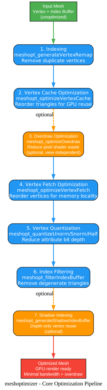
The pipeline diagram above shows the seven-stage optimization sequence that meshoptimizer recommends for maximizing GPU rendering efficiency. The order matters - each stage depends on the output of the previous one. Let’s walk through each stage:
Stage 1: Indexing
The first step is generating an index buffer from a raw vertex buffer (or reindexing an existing one). The meshopt_generateVertexRemap function creates a remap table based on binary equivalence of vertex data, eliminating duplicate vertices. This is essential because most downstream algorithms assume a deduplicated, indexed mesh. Without indexing, every triangle would carry three full vertex copies, wasting memory and bandwidth. The function also supports a custom variant (meshopt_generateVertexRemapCustom) that allows comparing attributes with tolerance, which is useful when floating-point drift has created near-duplicate vertices that should be merged.
Stage 2: Vertex Cache Optimization
When the GPU runs the vertex shader, it caches recent results in a post-transform cache (historically 16-32 vertices, now handled via batched thread groups). meshopt_optimizeVertexCache reorders triangles so that vertices referenced by nearby triangles are close together in the stream, maximizing cache reuse. The library uses an adaptive algorithm that works well across different GPU architectures rather than modeling a specific cache replacement policy. For faster iteration during content authoring, meshopt_optimizeVertexCacheFifo targets fixed-size FIFO caches and runs roughly 2x faster, though it generally produces slightly worse results on modern GPUs.
Stage 3: Overdraw Optimization (optional)
After vertex transformation, the rasterizer generates pixels that pass a depth test before the pixel shader runs. meshopt_optimizeOverdraw reorders triangles to minimize overdraw from all directions - this is a view-independent optimization, meaning it reduces average overdraw without knowing the camera position. A threshold parameter (recommended 1.05) controls how much vertex cache efficiency can be sacrificed for overdraw reduction. This optimization is not always beneficial: mobile GPUs with tiled deferred rendering (PowerVR, Apple) do not benefit, and vertex-heavy scenes may suffer from the reduced cache efficiency. Always measure before committing to this stage.
Stage 4: Vertex Fetch Optimization
Before the vertex shader runs, the GPU fetches vertex attributes from the vertex buffer in VRAM. meshopt_optimizeVertexFetch reorders the vertices in the vertex buffer to match the order they are first referenced by the index buffer, improving memory locality. This must be done after the final triangle order is established (i.e., after vertex cache and overdraw optimization), since the optimal vertex order depends on the triangle order. For multi-stream vertex layouts, meshopt_optimizeVertexFetchRemap is available instead.
Stage 5: Vertex Quantization
To reduce memory bandwidth and storage, vertex attributes can be quantized to smaller types. The library provides building blocks: meshopt_quantizeUnorm, meshopt_quantizeSnorm, and meshopt_quantizeHalf for converting float values to normalized integers or half-precision floats. Common patterns include quantizing normals to 10-bit SNORM (packed as 10_10_10_2), positions to 16-bit half-float, and texture coordinates to 12-bit unorm. The GPU dequantizes these via vertex input configuration, often requiring no shader changes. This is the only stage that introduces controlled quality loss.
Stage 6: Index Filtering
meshopt_filterIndexBuffer removes degenerate and duplicate triangles from the index buffer. Degenerate triangles (where two vertices map to the same position) are skipped by the rasterizer but still cost processing. Filtering after quantization is convenient because quantization can create new redundant triangles from positions that were similar but not identical before. This stage is especially valuable for ray tracing, where degenerate triangles waste intersection tests.
Stage 7: Shadow Indexing (optional)
Many rendering pipelines render meshes to depth-only targets (shadow maps, depth pre-pass) in addition to color targets. meshopt_generateShadowIndexBuffer generates a separate index buffer that treats vertices with identical positions as equivalent, reducing unique vertex count for depth-only rendering. This is most beneficial for meshes with many attribute seams (faceted shading, lightmap UVs). The resulting shadow index buffer should be optimized for vertex cache separately.
Key Insight: Why Order Matters
The pipeline order is not arbitrary. Indexing must come first because all other algorithms assume indexed meshes. Vertex cache optimization must come before overdraw because overdraw optimization is allowed to degrade cache efficiency by a controlled threshold. Vertex fetch must come after the triangle order is final. Quantization can increase redundant triangles, so filtering should follow it. Each stage’s output is the next stage’s optimal input.
Which GPU Stages Each Optimization Targets
To understand why each optimization matters, it helps to map them to the actual GPU pipeline stages they improve.
Understanding the GPU Pipeline Mapping
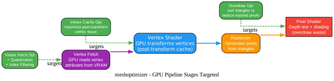
The diagram shows the four major GPU pipeline stages and which meshoptimizer algorithms target each one. This mapping explains why the optimizations are independent and additive:
Vertex Fetch Stage
The GPU reads vertex attributes from the vertex buffer in VRAM, typically backed by a memory cache. Three optimizations target this stage. Vertex fetch optimization reorders vertices for locality, so consecutive triangle references hit nearby memory. Quantization reduces the size of each vertex, so more vertices fit in a cache line. Index filtering removes degenerate triangles, which means fewer vertex fetches for triangles that would have been discarded anyway. Together, these reduce the memory bandwidth consumed by vertex fetch, which is often the bottleneck for large meshes.
Vertex Shader Stage
The GPU transforms vertices and stores results in a post-transform cache. Vertex cache optimization targets this stage by reordering triangles so that the same vertex is not transformed twice. On modern GPUs, vertex invocations are batched into thread groups, and effective reuse depends on the locality of vertex references in the index stream. By maximizing this locality, the adaptive algorithm ensures the post-transform cache hits as often as possible, reducing the number of vertex shader invocations. This is often the single most impactful optimization for vertex-heavy workloads.
Rasterizer Stage
The rasterizer converts triangles into pixels. This stage is not directly optimized by meshoptimizer, but it is the source of overdraw - pixels that are generated, pass or fail the depth test, and potentially waste pixel shader work. Overdraw optimization targets the rasterizer indirectly by sorting triangles so that front-facing surfaces are drawn first, causing more back-facing occluded triangles to fail the depth test early.
Pixel Shader Stage
The pixel shader runs for every pixel that passes the depth test. Overdraw means the pixel shader runs multiple times for the same screen pixel, with only the closest result visible. Overdraw optimization reduces this wasted work. On GPUs with early-Z testing, drawing occluders first allows the hardware to reject occluded fragments before the pixel shader runs. The view-independent overdraw optimization from meshoptimizer improves the average case across all viewing directions.
Why These Are Independent
Each optimization targets a different GPU stage, which is why they compose additively. Vertex cache optimization reduces vertex shader invocations. Vertex fetch optimization reduces memory bandwidth. Overdraw optimization reduces pixel shader invocations. Quantization reduces both bandwidth and storage. None of these conflict with each other (with the controlled exception of overdraw’s threshold on vertex cache efficiency), so applying all of them yields cumulative benefits.
Meshlet Clusterization for Modern Mesh Shaders
Traditional rendering feeds the GPU an index buffer and lets the fixed-function hardware assemble triangles. Modern GPUs (NVIDIA Turing+, AMD RDNA2+) introduce mesh shaders - a programmable geometry pipeline where the application provides batches of work directly to the rasterizer. To use mesh shaders efficiently, meshes must be split into meshlets: small clusters of triangles with their own vertex and micro-index data.
Understanding Meshlet Clusterization
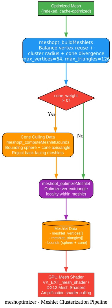
The meshlet clusterization diagram shows how meshoptimizer converts an optimized mesh into meshlet data ready for GPU mesh shading. Let’s break down each component:
meshopt_buildMeshlets
The core algorithm takes an indexed mesh and produces a series of meshlets, each containing a small set of vertices and a micro-index buffer. It balances three competing objectives: maximizing vertex reuse within each meshlet (topological efficiency), minimizing the meshlet radius (spatial compactness for culling), and minimizing triangle direction divergence (for cone culling). The recommended hardware limits are max_vertices=64 and max_triangles=126 for NVIDIA, though the README notes that 64/96 may be more realistic for real-world meshes and reduces overhead on other GPUs.
Cone Culling Data
When cone_weight is set above zero, the builder optimizes for cone culling - a technique where each meshlet gets a cone axis and cutoff angle. At runtime, if the camera lies within the cone, all triangles in the meshlet are guaranteed back-facing and the entire meshlet can be rejected without rasterizing any triangles. The meshopt_computeMeshletBounds function computes the bounding sphere (for frustum and occlusion culling) and the cone data. This is powerful for dense scenes where many meshlets face away from the camera.
meshopt_optimizeMeshlet
After building, each meshlet can be further optimized in isolation for better triangle and vertex locality. This improves the efficiency of the mesh shader’s internal vertex reuse. This is a fine-grained optimization that operates within the meshlet’s small vertex and triangle count.
GPU Mesh Shader Pipeline
The resulting meshlet data is uploaded to GPU buffers. At runtime, a mesh shader reads the meshlet for the current workgroup, transforms its vertices, and outputs triangles to the rasterizer. An amplification (task) shader can run cluster culling at a lower frequency before dispatching mesh shader workgroups, rejecting invisible meshlets before they are processed. This two-level culling (amplification shader culls meshlets, mesh shader renders survivors) is the key performance advantage of the mesh shader pipeline over traditional rendering.
Spatial Clustering for Ray Tracing
For ray tracing, meshoptimizer provides meshopt_buildMeshletsSpatial, which uses a surface area heuristic (SAH) to produce raytracing-friendly cluster distributions. This recursively subdivides triangles into a BVH-like hierarchy, producing clusters that minimize ray-triangle intersection tests. This is important for ray tracing where the cost model differs from rasterization: spatial coherence matters more than triangle count. The resulting clusters can be used to build cluster acceleration structures (via VK_NV_cluster_acceleration_structure) that can be updated individually without rebuilding the entire BLAS.
Key Insight: Nanite-Style Rendering
Meshlet clusterization is the foundation of Nanite-style rendering (as pioneered by Unreal Engine 5). By splitting meshes into small clusters, you gain fine-grained culling, per-cluster LOD selection, and the ability to update geometry at the cluster level. meshoptimizer provides the building blocks: clusterization, partitioning (meshopt_partitionClusters), and position quantization (meshopt_computePositionExponent) for cluster-relative encoding. Combined with the simplification system, this enables hierarchical LOD systems where each level of detail is a coarser clusterization of the same mesh.
Mesh Simplification and LOD Generation
The most effective way to reduce rendering cost is to reduce the triangle count. meshoptimizer provides a family of simplification algorithms that generate lower-detail versions of a mesh for use at greater viewing distances.
Understanding Mesh Simplification
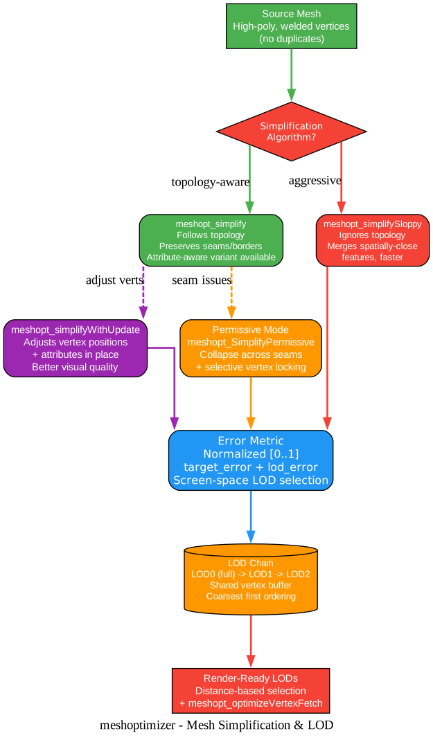
The simplification diagram shows the decision tree for choosing the right simplification algorithm and the LOD generation workflow. Let’s examine each path:
meshopt_simplify (Topology-Aware)
The standard simplifier follows the topology of the original mesh, collapsing edges in order of increasing error. It preserves attribute seams, borders, and overall appearance because it cannot collapse vertices across discontinuities inferred from the index buffer. This produces the highest quality LODs but can get “stuck” on meshes with many seams (e.g., faceted normals from flat shading) where it cannot find legal collapses. The input mesh must have welded vertices (no duplicates) for the simplifier to work well.
meshopt_simplifySloppy (Topology-Ignoring)
When topology gets in the way, meshopt_simplifySloppy ignores the mesh topology and merges features that are spatially close but topologically disjoint. This produces meshes with worse geometric and attribute quality, but it can always reach the target triangle count. It is useful for aggressive simplification where visual quality is less important than hitting a budget, or as a fallback when the standard simplifier gets stuck.
Attribute-Aware Simplification
meshopt_simplifyWithAttributes takes additional attribute data (normals, texture coordinates, vertex colors) with per-attribute weights. The simplifier then minimizes both positional error and attribute error. This improves shading quality (normals), texture deformation (UVs), and color preservation. For normalized attributes, a weight around 1.0 is typical; for texture coordinates, 10-100 depending on UV density. The combined error metric can be used for LOD selection that accounts for attribute quality, not just position.
Permissive Mode with Selective Locking
The meshopt_SimplifyPermissive option relaxes the seam-preservation constraint, allowing collapses across attribute discontinuities when the resulting error is acceptable. Combined with selective vertex locking (meshopt_SimplifyVertex_Protect), you can protect specific seams (like UV boundaries) while allowing others to collapse. This often produces higher quality LODs than either the strict or sloppy approaches, because it gives the simplifier freedom where it is safe while preserving appearance where it matters.
Simplification with Vertex Update
meshopt_simplifyWithUpdate goes a step further by adjusting vertex positions and attributes in place after collapsing. This produces better visual quality at aggressive simplification levels because the remaining vertices can be repositioned to minimize the deviation from the original surface. The trade-off is that the original vertex data is modified, so a copy must be made if the original mesh is still needed.
Error Metric and LOD Selection
All simplification functions return a normalized error in the [0..1] range, where 1.0 represents the full mesh extent. This error can be converted to object space via meshopt_simplifyScale, and used for distance-based LOD selection. The recommended approach: compute the screen-space error per pixel, compare it against the LOD’s error, and switch to a coarser LOD when the error would be smaller than one pixel. This ensures the user never sees popping while minimizing triangle count.
LOD Chain Construction
When generating a chain of LODs that share a vertex buffer, order matters for mobile GPUs that can only transform sequential vertex ranges. The recommended approach: optimize each LOD for vertex cache independently, then concatenate them in one large index buffer starting from the coarsest LOD, and run meshopt_optimizeVertexFetch on the final combined buffer. This ensures coarser LODs require smaller vertex ranges and are efficient for vertex fetch and transform.
Mesh Compression
Beyond optimization, meshoptimizer provides lossless encoding for vertex and index data that reduces storage and transmission size while remaining compressible by general-purpose compressors.
Vertex Encoding
meshopt_encodeVertexBuffer exploits the locality of sequential vertices and identifies repeating bit patterns in consecutive vertices. The codec is lossless - the only lossy step is quantization applied before encoding. The decoder runs at 3-6 GB/s on modern desktop CPUs and can target write-combined memory directly. Compression ratios of 2-4x are typical compared to already-quantized data, and general-purpose compressors (LZ4, zstd, Oodle) can further improve the ratio.
Index Encoding
meshopt_encodeIndexBuffer encodes triangle indices by exploiting vertex cache coherence. It preserves triangle order but can rotate each triangle to improve compression. Like the vertex codec, the decoder runs at 3-6 GB/s. This encoding is available as the glTF extension EXT_meshopt_compression, making it a standard part of the glTF ecosystem.
Why Not Just Use zstd?
General-purpose compressors are not designed to exploit the specific redundancies in vertex and index data. They cannot predict the next vertex from the previous one, nor can they exploit the index buffer’s cache-coherent access patterns. meshoptimizer’s codecs are domain-specific: they understand that consecutive vertices tend to be similar, and that consecutive indices tend to reference nearby vertices. This is why encoding the data with meshoptimizer first, then applying zstd, yields better ratios than zstd alone.
Installation
meshoptimizer is a single-header C/C++ library. You can use it via CMake or by adding source files directly to your build.
Option 1: CMake
git clone -b v1.2 https://github.com/zeux/meshoptimizer.git
cd meshoptimizer
mkdir build && cd build
cmake ..
cmake --build . --config Release
Option 2: Add Source Files
The source files in src/ are organized so you only need to add the files for the algorithms you use. Include the header in your code:
#include "meshoptimizer.h"
The header is C-compatible, so it can be used from C or C++. The source files are C++ but build without warnings on all major compilers.
Package Managers
meshoptimizer is available on several package managers:
- Linux: ArchLinux AUR, Debian, FreeBSD, Nix, Ubuntu
- Vcpkg:
vcpkg install meshoptimizer - Conan:
conan install meshoptimizer
Usage
Core Optimization Pipeline
#include <vector>
#include "meshoptimizer.h"

struct Vertex {
    float x, y, z;
    float nx, ny, nz;
    float u, v;
};

// 1. Indexing (deduplicate vertices)
size_t index_count = face_count * 3;
size_t unindexed_vertex_count = face_count * 3;
std::vector<unsigned int> remap(unindexed_vertex_count);
size_t vertex_count = meshopt_generateVertexRemap(
    remap.data(), nullptr, index_count,
    unindexed_vertices.data(), unindexed_vertex_count, sizeof(Vertex));

std::vector<unsigned int> indices(index_count);
std::vector<Vertex> vertices(vertex_count);
meshopt_remapIndexBuffer(indices.data(), nullptr, index_count, remap.data());
meshopt_remapVertexBuffer(vertices.data(), unindexed_vertices.data(),
    unindexed_vertex_count, sizeof(Vertex), remap.data());

// 2. Vertex cache optimization
meshopt_optimizeVertexCache(indices.data(), indices.data(),
    index_count, vertex_count);

// 3. Overdraw optimization (optional)
meshopt_optimizeOverdraw(indices.data(), indices.data(), index_count,
    vertices.data()->x, /* TODO */ vertex_count, sizeof(Vertex), 1.05f);

// 4. Vertex fetch optimization
meshopt_optimizeVertexFetch(vertices.data(), indices.data(),
    index_count, vertices.data(), vertex_count, sizeof(Vertex));
Meshlet Generation
const size_t max_vertices = 64;
const size_t max_triangles = 126;
const float cone_weight = 0.25f;

size_t max_meshlets = meshopt_buildMeshletsBound(
    indices.size(), max_vertices, max_triangles);
std::vector<meshopt_Meshlet> meshlets(max_meshlets);
std::vector<unsigned int> meshlet_vertices(indices.size());
std::vector<unsigned char> meshlet_triangles(indices.size());

size_t meshlet_count = meshopt_buildMeshlets(
    meshlets.data(), meshlet_vertices.data(), meshlet_triangles.data(),
    indices.data(), indices.size(),
    vertices.data()->x, vertices.size(), sizeof(Vertex),
    max_vertices, max_triangles, cone_weight);

// Trim to actual size
const meshopt_Meshlet& last = meshlets[meshlet_count - 1];
meshlet_vertices.resize(last.vertex_offset + last.vertex_count);
meshlet_triangles.resize(last.triangle_offset + last.triangle_count * 3);
meshlets.resize(meshlet_count);
Simplification
float threshold = 0.2f;
size_t target_index_count = size_t(index_count * threshold);
float target_error = 1e-2f;

std::vector<unsigned int> lod(index_count);
float lod_error = 0.f;
lod.resize(meshopt_simplify(lod.data(), indices.data(), index_count,
    vertices.data()->x, vertex_count, sizeof(Vertex),
    target_index_count, target_error, 0, &lod_error));
Features
| Feature | Description |
|---|---|
| Vertex cache optimization | Reorder triangles for GPU post-transform cache reuse |
| Overdraw optimization | View-independent triangle sorting to reduce pixel shader waste |
| Vertex fetch optimization | Reorder vertices for memory locality |
| Vertex quantization | Reduce attribute bit depth (unorm, snorm, half-float) |
| Index filtering | Remove degenerate and duplicate triangles |
| Shadow indexing | Separate index buffer for depth-only rendering |
| Meshlet clusterization | Split meshes into GPU-friendly clusters for mesh shaders |
| Cone culling | Per-meshlet back-face culling data |
| Spatial clustering | SAH-based meshlets for ray tracing |
| Mesh simplification | Topology-aware, sloppy, attribute-aware, and permissive modes |
| LOD generation | Error-metric-driven level-of-detail chains |
| Vertex encoding | Lossless vertex compression (2-4x ratio) |
| Index encoding | Lossless index compression (2-4x ratio) |
| Cluster partitioning | Group meshlets into larger partitions for batched processing |
| Position quantization | Cluster-relative encoding for DXR2 Compressed1 format |
| gltfpack | Companion CLI tool for optimizing glTF files |
| Single-header | C-compatible header, C++ source, no dependencies |
Troubleshooting
Simplifier gets stuck and cannot reduce triangle count
This usually means the mesh has many attribute seams (e.g., faceted normals from flat shading) that prevent the simplifier from collapsing vertices across discontinuities. Solutions: (1) weld vertices before simplifying, (2) use permissive mode (meshopt_SimplifyPermissive) with selective vertex locking, or (3) use meshopt_simplifySloppy for aggressive simplification that ignores topology.
Poor compression ratios from vertex encoding
The vertex encoder assumes the vertex buffer was optimized for vertex fetch and that vertices are quantized. Feeding unoptimized, unquantized data results in poor ratios because the codec cannot exploit locality or small integer ranges. Always run the full optimization pipeline (especially vertex fetch optimization and quantization) before encoding.
Overdraw optimization makes performance worse
Overdraw optimization trades vertex cache efficiency for overdraw reduction. If your scene is vertex-bound (not fill-rate-bound), the reduced cache efficiency may outweigh the overdraw savings. Additionally, mobile GPUs with tiled deferred rendering (PowerVR, Apple) do not benefit from overdraw optimization at all. Measure before and after, and disable this stage if it hurts performance.
Meshlet cone culling rejects too many meshlets
The cone_weight parameter controls the balance between cone culling efficiency and other forms of culling. If cone culling is too aggressive, lower the weight (try 0.1 or 0.0). A weight of 0 disables cone optimization entirely, while 0.25 is a reasonable default when cone culling is used alongside frustum and occlusion culling.
Degenerate triangles remain after index filtering
Index filtering only removes triangles where two vertices map to the same position. If your vertex shader displaces vertices (e.g., instancing, skinning), triangles that are non-degenerate in object space may become degenerate after shading. For deformable meshes, include skinning data in the vertex portion used as the key for meshopt_filterIndexBuffer, or use meshopt_filterIndexBufferMulti for non-contiguous data.
Conclusion
meshoptimizer is a rare example of a library that is both production-critical and academically interesting. Its algorithms are grounded in the realities of GPU hardware - post-transform caches, memory locality, rasterizer behavior - and refined through years of real-world use in game engines and content tools. The seven-stage optimization pipeline is a masterclass in how to think about GPU performance: identify the bottleneck stage, optimize the data for that stage, and compose the optimizations additively.
The meshlet clusterization system points to the future of rendering. As mesh shaders become mainstream, the traditional index-buffer-plus-vertex-shader model is giving way to cluster-based rendering where the application controls geometry processing at a finer granularity. meshoptimizer provides the foundation: clusterization, culling data, partitioning, and position quantization. Combined with the simplification system, this enables Nanite-style hierarchical LOD on any engine willing to implement the rendering side.
For anyone working in real-time 3D graphics - whether in game engines, CAD viewers, or web-based renderers - meshoptimizer is an essential tool. It is MIT-licensed, dependency-free, and runs everywhere from desktops to mobile to webAssembly. The companion gltfpack tool makes it accessible without writing any code, while the C/C++ API gives engine developers full control over the optimization pipeline.
Links
Related Posts
- PyShine Screen Recorder: Native C++ Engine for Perfect A/V Sync
- Needle 2: 14MB Foundation Model for Tiny Devices

Enjoyed this post? Never miss out on future posts by following us


